


Just like any led display control system, sometimes after a long time of operation, the control card may lose the configuration file (“.rcfg” file if NOVASTAR) and couldn’t get it from the original supplier. In this case, you’d need to set the parameters in the program and configure the new file.
Here we will explain how to configure this file.
1. Collect basic tech parameters of the led display hardware.
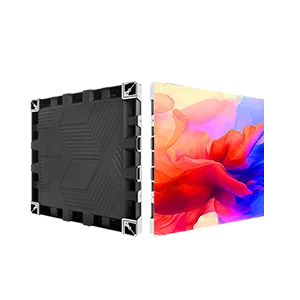
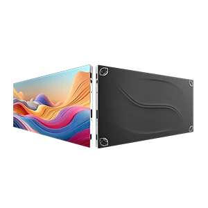
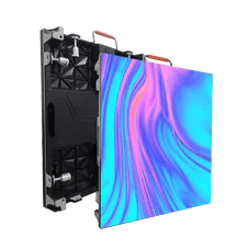
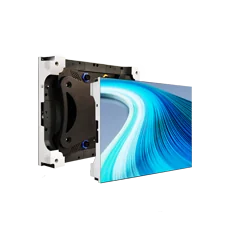
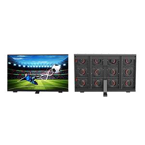
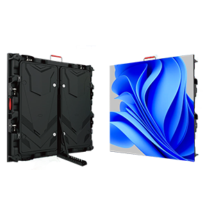
For instance, here we have two led cabinets with P10 SMD LED modules, then we install asynchronous NOVASTAR control cards, one sending card, two receive cards on them.
And I connect the sending card to the laptop with the net cable.

And the basic tech parameters of this led display are:

- This P10 SMD LED screen consists of 2 cabinets. When I face it, the signal transfer sequence is from right to left.
- Each cabinet consists of 9 modules 3(W)*3(H).
- The size of each LED module is 320mm X 320mm, with the resolution of 32pixels X 32 pixels.
- The resolution of this LED screen is 192 pixels X 96 pixels.
2. Install the software of NOVASTAR control system.
NovaLCT-Pluto and Pluto Manager is the software that you need to install for NOVASTAR asynchronous control system.
Note: NOVASTAR synchronous control system and asynchronous control system use different software. Refer below:

3. Configure the NOVASTAR asynchronous control card.
1. Open the software NovaLCT-Pluto, connect the sending card to the laptop with a net cable. And click “Search All Site(S)”.

Probably you would not find the sending card.

So you’d need to check the IP of the Laptop, and change it to be “192.168.0. XXX” – the IP of the laptop must be in the same net segment with the IP of the sending card so that the communication between them (computer and control card) could happen.
Here I change the IP address of my laptop as below:

And also change the relevant place in the software:


Now search the control card again, and this time you could find it.

Click “connect terminal”, the laptop will be connected to the sending card.
Note: The default IP address of sending card is “192.168.0.208” which is defined in the factory, usually we don’t change it.
2. User login. Key in password “admin”, and you would enter the “screen config” interface.


After User Login, we can start to configure the control card.

Enter “smart setting” interface.

3. Start “smart setting”. Here you need to input the basic tech parameters of the LED screen.


- Chip type: choose “common chip”.
- Actual pixel: That’s the LED module resolution. As mentioned above, in this sample, each LED module is 32pixels X 32 pixels.
- Scan type: It’s OK to choose “unknown”if you don’t know it. (Actually, there’s simple way to know the scan type. If you want to learn this, please contact us.)
- Cols: each cabinet has 3X3 modules. So key in 3, 3.
- Module cascade type (from the front): We explained at the first ste when watch from the front, the signal transfer sequence is from right to left.
After you’ve filled all those tech parameters, press “Next”
4. In following steps, you need to watch the LED screen’s change, and then make the right choice of what you see.


Choose “Black”, press “Next”. And it will get into “Auto switch status”.

When the LED screen shows the right colors, click “Next”

Total 8 rows were lighting, so key in “8”, and click “Next”

According to the picture above, key in “4”, and click “Next”.
Note: if we choose “1/2” as the “scan type” but not “unknown”, this step will be skipped. So now you know that when you key in “4”, it means we are “telling” the control card that the LED modules are with 1/2 scan mode.
5. In this step, we can see on the LED display screen, at first, there is one pixel brighten. (we mean only the white color)

Then we can find the location of the white pixel in below chart accordingly – row 5, column 8, that is position “A”.

Now follow the sequence of the brighten pixel shown on the LED display screen, click the correspondent position on the chart one by one to finish this process.

6. Now, the smart setting is accomplished. Next we are going to do “screen configure”.
In this step, we will define the sequence of the receiving cards.
We have 2 receiving cards. So it’s very easy to configure them.

When we input Scan Board Columns “2” and Scan Board Rows “1”
In the area below it will appear two square areas represent 2 receiving cards.
The width and height of Scan Board Size means the resolution of the led cabinet.
Here it is 96X96 pixels.

The arrow in the black square means the sequence of receiving card is from right to left.
And click “send to HW”

The configuration of the NOVASTAR asynchronous control card is now finished.
For further information, please email sales@ledful.com